40 wiring diagram motion sensor
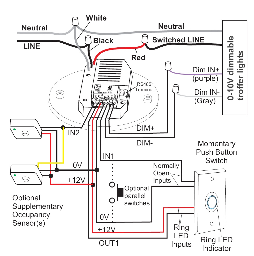
Wiring a Motion Detector Head to an Existing Light Fixture. Here is an existing fixture that can have a motion detector head added to it to provide automatic sensor control during the night time. All wiring is done after identifying and turning the circuit off. Connect sensor red dimming wire with lamp purple dimming wire by using wire nut. 13. Connect sensor black dimming wire with lamp gray dimming wire by using wire nut. 14. Review completed sensor wiring configuration for accuracy, using wiring diagram. MOTION SENSOR INSTALLATION 15. Place junction box and bracket on the fixture. Align screw holes.
Zenith motion sensor wiring diagram. The actual light is separate and already connected. A remote sensor automatically lights up dark sidewalks and yards. And itll operate any light fixture. Outside lights to motion sensor lights handyman wire handyman usa more information find this pin and more on backyard work shop and projects by bill yarbrough.

Wiring diagram motion sensor
About Motion Pir Diagram Sensor Wiring . This driver is used to control stepper-motors such as NEMA 17. Order online at Screwfix. Parallel link is more complex compared to series one. Staircase Wiring circuit diagram & working. Power it up and wait 1-2 seconds for the sensor to get a snapshot of the still room. Set the two adjustment knobs on the sides of the sensor (Diagram C) to the.Packed with features that have made Clipsal the leader in Passive Infrared (PIR) motion sensor technology, the new Series Indoor Infrascan is the next Wiring diagram 1 (a), without override. Pir Motion Sensor Light Wiring Diagram New Wiring Diagram For A Pir - Motion Sensor Light Wiring Diagram Wiring Diagram consists of many detailed illustrations that display the relationship of varied items. It includes guidelines and diagrams for various varieties of wiring techniques and other items like lights, home windows, and so forth.
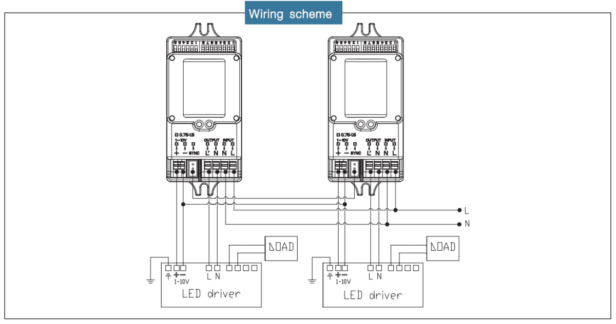
Wiring diagram motion sensor. Comprehensive LED shoebox light wiring diagram with step-dimming mircrowave motion sensor and photocell sensor for outdoor street, parking lot lighting. Skip to navigation Skip to content sales@chiuer.com (806) 680-3682 300 W Airtex Blvd, Suite 100, Houston, Texas 77090 Leviton Motion Sensor Light Switch Wiring Diagram December 26 2020 1 Margaret Byrd. 4 wire motion sensor light wiring diagram. But it does not imply connection between the cables. A quick video showing you how to wire a motion sensor up to an LED lightMotion sensors are great in areas where a light switch is not practical. Nov 04, 2018 · Graphic 7d088 2005 Silverado Engine Diagram Digital Resources 2004 Gmc Truck Engine Diagram Car Engine Diagram 1995 … Read Online Motion Sensor Light Switch Wiring Diagram room—simply replace light switches with hands-free motion …A motion sensor night light can be a smart addition to a child's
Wiring a motion sensor light diagram source. These instructions will be easy to comprehend and apply. Connect the red wire from the motion sensor to the other junction box s live wire. Put a plastic wire nut on top of the ends to hold them together. If not the structure will not work as it should be. Some motion sensors have an easy-to-read wiring diagram on the back that shows you which wires to connect. The neutral wire on the motion sensor can also be blue or green instead of white. 4 Connect the red wire from the motion sensor to the other junction box's live wire. ANALOG SPEED SENSOR Uses magnetic impulses to open and close a switch to create a signal for ... Toyota Wiring Diagram Symbols. Appendix A A-2 TOYOTA Technical Training IGNITION SWITCH ... motion. SWITCH, WIPER PARK Automatically returns wipers to the stop position Most motion sensors installed for security systems operate on 12V DC power and are connected to four wires: two for power and two for the motion signal. Red and black wires are usually the positive and negative power wires respectively. The other pair of wires could be any color and carry the motion detection signal.
- Motion Sensor Light Switch Wiring Diagram Wiring Diagram comes with a number of easy to stick to Wiring Diagram Directions. It is intended to help all of the average user in creating a correct method. These instructions will probably be easy to understand and apply. MERCEDES BENZ W210 Wiring Diagrams 1995-2001 W210 Starter and Generator (Engines 104, 111, 604, 605, 606) Wiring Diagram W210 Speed Signal of the Front Axle (GES) (Engines 104, 111, 602, 604, 605, 606) Schematics A quick video showing you how to wire a motion sensor up to an LED light.Motion sensors are great in areas where a light switch is not practical. Motion sens... Wiring Diagram CAUTION: Both lights must be powered from the same circuit. If not connected as shown, you may destroy both lights and void your warranty. 2008 HeathCo LLC 850-1000-00 White Black Green or Bare Light Fixture (Motion) Light Fixture (Standard) Red Bowling Green, KY 42101
How to Choose Wood Flooring
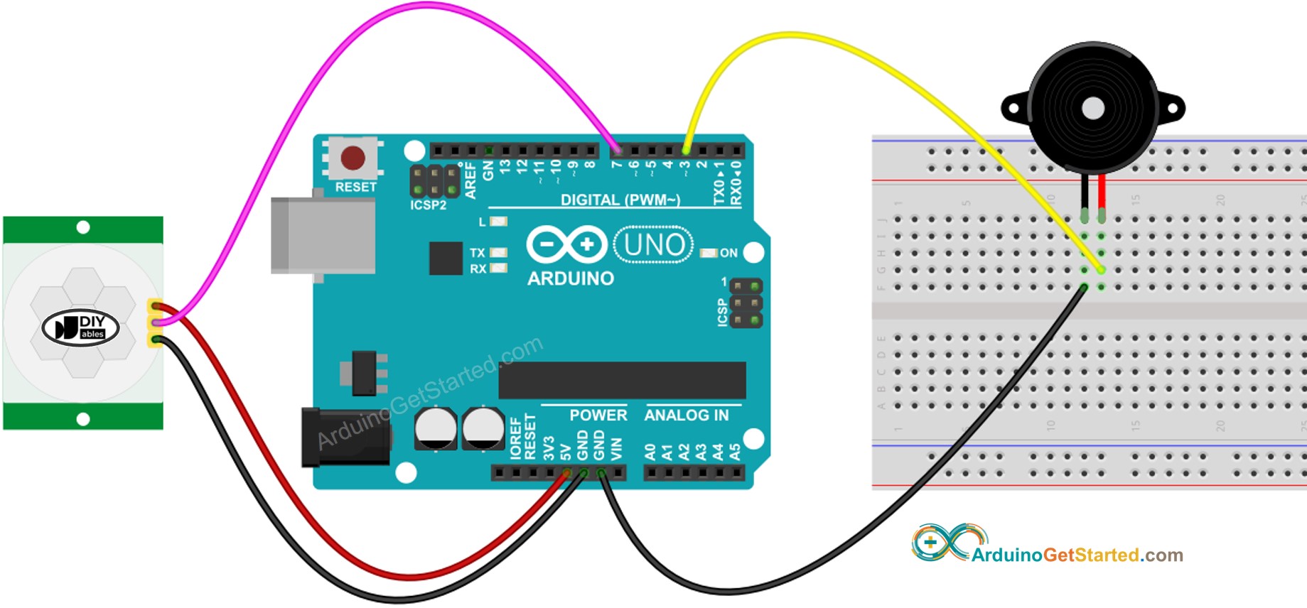
Learn: how HC-SR501 motion sensor works, how to connect motion sensor to Arduino, how to code for motion sensor, how to program Arduino step by step. The detail instruction, code, wiring diagram, video tutorial, line-by-line code explanation are provided to help you quickly get started with Arduino. Find this and other Arduino tutorials on ArduinoGetStarted.com.

motion sensor wiring diagram Questions & Answers (with ...
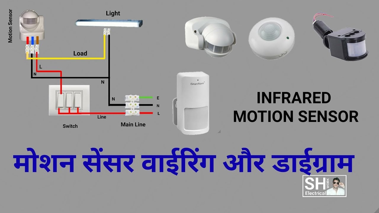
Typical Wiring Connections for a Security Light Sensor Black Wire Is the LINE or the Incoming Circuit Power. Red Wire Is the LOAD, or the Outgoing Power to the Light Fixture. White Wire Is the Neutral Wire which is typically shared or connected with the light fixture and the Sensor or Detector. Green Wire or Bare Wire

PIR Motion Sensor Switch / Vtac - YouTube | Motion sensor ...
Diy Pir Infrared Motion Sensor Switch Smart Security Led Light - Motion Sensor Wiring Diagram Wiring Diagram consists of numerous in depth illustrations that display the relationship of varied things. It consists of guidelines and diagrams for various kinds of wiring techniques along with other items like lights, home windows, etc.

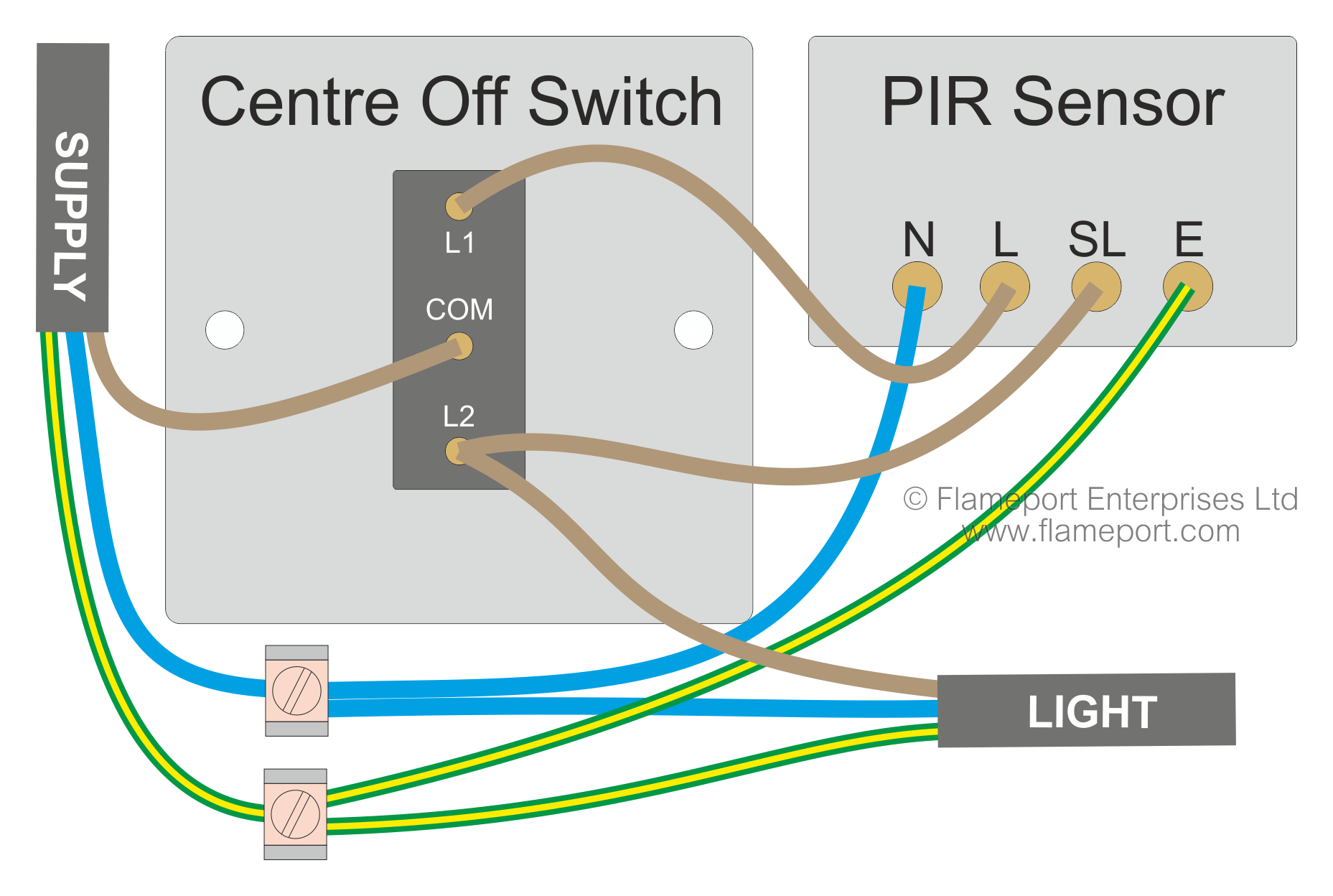
PIR Sensor Security Light & Switch
Refer to the wiring diagrams and install the sensor according to these directions For single pole applications, wire the sensor switch according to wiring diagram #1 using the wire nuts provided. OS306U Motion Sensor Switch (Auto ON/Auto OFF) VS306U Motion Vacancy Sensor Switch (Manual ON/Auto OFF) ENGLISH

Connect PIR Motion Sensor and ESP32 to AskSensors over MQTT ...
Here is my wiring diagram ( third photo) and instructions: CAUTION: BLACK WIRE IS 120 VOLTS, SO TURN OFF SWITCH OR CIRCUIT BREAKER. Connect sensor's black wire to black wire coming from house. Connect red sensor wire to light's black wire . Connect all 3 white wires (from house, from sensor and from light) together. Now wasn't that easy.

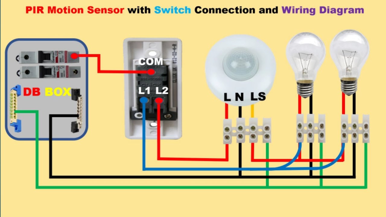
PIR Motion Sensor Wiring and Connection Diagram for ...
Black wires from lights connect to red wire from motion sensor/ Cap this connection/ it is ... Use same diagram shown above, except there is not white wireLarger image: Photocell instead of motion; Lea...

Wiring your Motion Sensors : Konnected Help & Support
Online Library Motion Sensor Light Switch Wiring Diagram wiring, residential smoke detectors, and systems covered in Article 800 of the NEC, such as telephone, cable TV, and broadband. With easy-to-read text and detailed illustrations, this text addresses specific challenges room by room, including AFCI protection for bedrooms,

Wiring diagram Electrical Wires & Cable Passive infrared ...
Attach the black wall wire to the motion sensor's own black wire. Once you do, secure both tightly using a wire connector. Then, use electrical tape to wrap around the connection and keep it safe. Step 9: The White Wires. The white wire of the wall must connect to the motion sensor's white wire.
How to Install Motion Sensor Light - Full Guidelines
After drywall is installed, the motion sensor can be attached to the stud or drywall with screws and plastic anchors. Types of Motion Detector Wiring. Motion detectors typically use 22-gauge, 4-conductor unshielded wiring. As with all alarm system wiring, both solid and stranded types are acceptable.

Motion sensor lights, Motion sensor lights outdoor, Light sensor
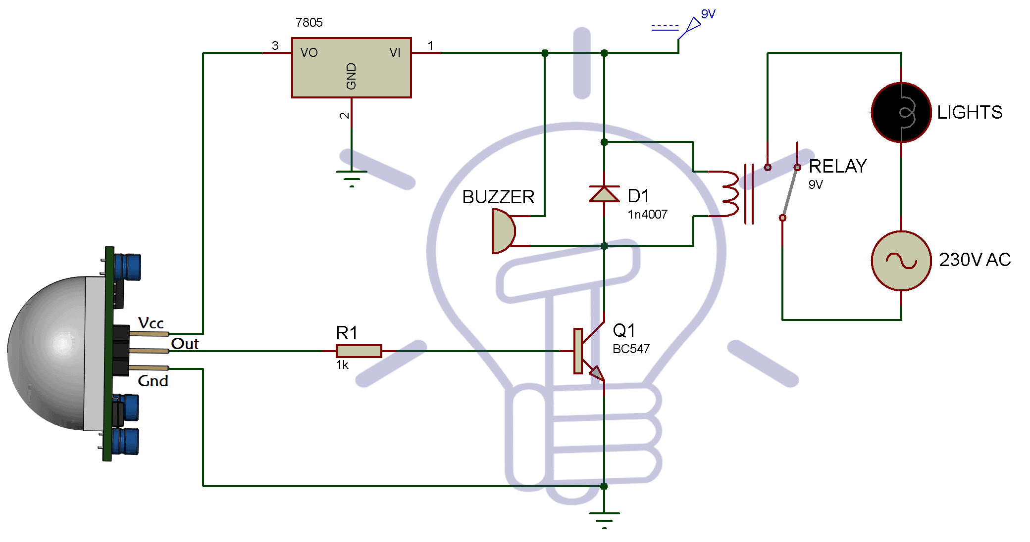
Note: – PIR sensor only detect the presence of the infrared rays which comes into its range, it does not emit infrared. Related Post: Simple Touch Sensitive Switch Circuit using 555 Timer & BC547 Transistor Working of Motion Detector Circuit. The PIR sensor typically operates at 5V, so we are using a positive voltage regulator IC 7805, which will give 5V output to feed the …

Elegant Wiring Diagram Ceiling Light #diagrams #digramssample ...
4 wire motion sensor light wiring diagram. It reveals the elements of the circuit as streamlined shapes and also the power and also signal connections between the tools. In basic installations you will only need to worry about connecting three wires. Light wiring diagram database. The hotwire the neutral wire and the ground wire.
Arduino - Motion Sensor - Piezo Buzzer | Arduino Tutorial
Download File PDF Motion Sensor Light Switch Wiring Diagram How To Wire a Outdoor Sensor for a Security Light AMIR Motion Sensor Light . AMIR Motion Sensor Lights act like little 'guardians', provide automated, hands-free way to protect your homes indoors and outdoors. Light up your bedroom, stairs, hallway, closet, or entryway
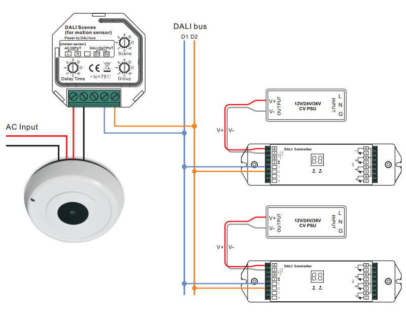
DALI Scene Controller for Motion Sensor SR-2412-Scenes
Wiring diagram 1 (a), Installation Instructions - & R Indoor infrascan - . WPR Motion Infrared Sensor Sensor, 10A, 3 Wire, Outdoor, Grey. The Clipsal Series Outdoor Infrascan is a highly reliable, state-of-the-art passive infrared (PIR) motion sensor.

PIR motion sensor light switch Auto Lights ON/OFF When detect the Movement at Night Time Wiring
When you look on the back of the motion sensor light switch there might be five wires that appear like they should be connected somewhere. These wires include the three basic wires always present in switches, and sometimes two more wires for three-way switching. Those two wires will usually have some sort of label attached to them as well.
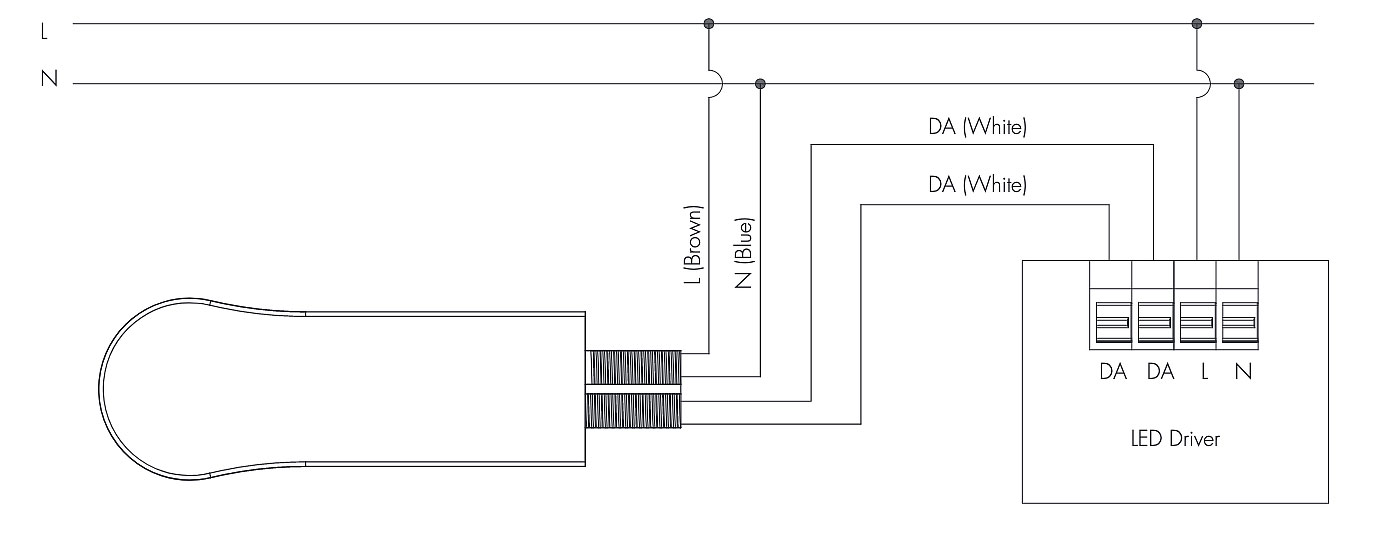
HCD049 DALI PIR Motion Sensor - IP65 - Hytronik Nordic
Take the copper wire from the black insulated wire in the motion sensor and twist it with the black wire that comes from the fuse or the power supply's circuit breaker. 16. Cover the wiring with a plastic wire nut. 17. Lastly, connect the bare ground copper wire with the metal housing in the light fixture. 18.
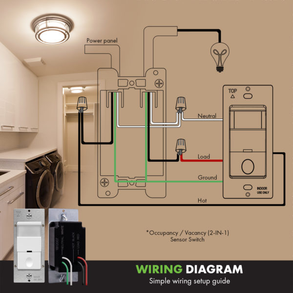
In-Wall PIR Occupancy/Vacancy Motion Sensor Switch, Neutral Wire Required
Motion Sensor. The drawing tool, Visual Paradigm Online (VP Online), supports Wiring Diagram, UML, ERD and Organization Chart. You can draw Wiring Diagram quickly through the intuitive drawing editor. Edit this Template.

Passive Infrared Sensor Motion Sensors Wiring Diagram PNG ...
This sensor is a motion switch with insufficient natural light the sensor switches on the light automatically when people enter in to the detection range. wi...
jual Mini Closet PIR Sensor Detector Smart Switch 110V 220V LED PIR Infrared Motion Sensor
Aug 11, 2017 · Throttle Position Sensor Wiring Diagram 1997 1998 Ford 4 6l 5 4l Repair Guides Repair Guides Circuit Diagram Throttle Position Sensor Placement And Wiring Junk Yard Zetec 1993 1995 Tps Wiring Diagram Jeep Grand Cherokee 4 0l Repair Guides 446 4 Wire Throttle Position Sensor Diagram Wiring Resources ...

RuggedGrade Lighting
Sensor. 3. 5. 1. 4. 3-Way Switch. 2. 1. 5. 4. 3. B Sensor is located in electrical box with LOAD connection: WIRING SWITCH: Connect wires per WIRING DIAGRAM ...2 pages
Pir Motion sensor Light Switch for House / 2WAY Switch connection and wiring Diagram/Electric House
Figure 2 is a line drawing of the wiring of 3 motion sensors to a group of lights and Figure 3 is a diagram of the actual wiring connections. You can have as many motion sensors as you want in parallel. Figure 2 - Schematic wiring diagram for multiple motion detectors with 120VAC lighting

Wiring diagram Occupancy sensor Electrical Wires & Cable ...
Jul 12, 2019 · Wiring – Connecting HC-SR501 PIR motion sensor to Arduino UNO. By connecting the motion sensor to a microcontroller like the Arduino UNO, you can use it to control all kinds of things: LEDs, relays, motors, buzzers etc. In the wiring diagram below, you can see how to hook it up to the Arduino.

Samxu Motion Sensor Switch AC 110V-240V, Automatic Dusk to Dawn Infrared Body Motion PIR Sensor, 180 Degree Motion Security Floodligh
Jan 20, 2022 · OVERALL ELECTRICAL WIRING DIAGRAM. ... By pressing the brake pedal, the current flowing to TERMINAL 8 of the light failure sensor keeps the warning circuit on and holds the warning light on until the ignition SW is turned off. [P] O …

PIR LED Security Light Circuit
More wiring diagram templates are available inside the wiring diagram tool. Motor Starter. Power Supply Specifications. Simple Wiring Diagram. Wiring Diagram Example. Motion Sensor. Feature Highlights. Communicate and collaborate faster than ever with the best online diagram tool around. Diagram with Ease. Drag and drop shapes to create ...

Electrical – I'm replacing an old 3-wire motion sensor with a ...
Pir Motion Sensor Light Wiring Diagram New Wiring Diagram For A Pir - Motion Sensor Light Wiring Diagram Wiring Diagram consists of many detailed illustrations that display the relationship of varied items. It includes guidelines and diagrams for various varieties of wiring techniques and other items like lights, home windows, and so forth.
Choifoo WS-EU-MW-xC (Radar Motion Sensor Switch) – eWeLink ...
Set the two adjustment knobs on the sides of the sensor (Diagram C) to the.Packed with features that have made Clipsal the leader in Passive Infrared (PIR) motion sensor technology, the new Series Indoor Infrascan is the next Wiring diagram 1 (a), without override.

Clarify light sensor wiring diagram - Home Improvement Stack ...
About Motion Pir Diagram Sensor Wiring . This driver is used to control stepper-motors such as NEMA 17. Order online at Screwfix. Parallel link is more complex compared to series one. Staircase Wiring circuit diagram & working. Power it up and wait 1-2 seconds for the sensor to get a snapshot of the still room.

Mini PIR Sensor Detector Smart Switch 85V 220V LED PIR Sensor Gerak Infra Merah Deteksi Otomatis Saklar Sensor Cahaya
Motion sensor wiring with switched override feature

Occupancy (motion) switch wiring question - Home Improvement ...

Stand alone pir sensor wiring diagram. How to wire up two ...
Motion Sensor | Wiring Diagram Template

ECOELER 3 Way Motion Sensor Light Switch Installation Guide ...
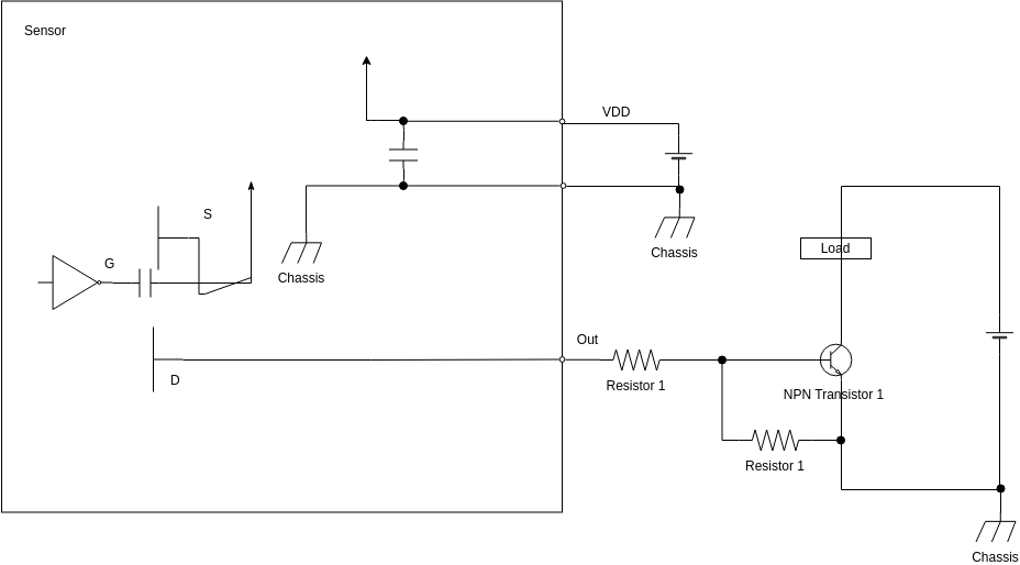
Implementing ALEC -

Motion-controlled Lamp (Without a Microcontroller) - Hackster.io
PIR Sensor Based Motion Detector / Sensor Circuit Diagram

Occupancy Sensor - ODS10-IDW

Occupancy Sensor - ODS10-I3W
Infrared Motion Detector Circuit - Circuit Diagram, Working ...

Sensor Gerak, Diagram, Diagram Pengkabelan gambar png
How to Install PIR Motion Sensor connection & Diagram
![Jual OEM Big Flexible PIR Motion Sensor [220V] - Hitam di ...](https://www.static-src.com/wcsstore/Indraprastha/images/catalog/full//96/MTA-7676151/oem_220v_big_flexible_pir_motion_sensor_-_sensor_gerak_infra_merah_full03_m9z2ircb.jpg)
Jual OEM Big Flexible PIR Motion Sensor [220V] - Hitam di ...
Sensor Wiring Diagram Motion Detection, PNG, 512x512px ...

Heath Zenith Motion Sensing Decorative Light Installation ...

Eaton OS306U-W-K-L Single-Pole/3-Way White Occupancy Motion ...
0 Response to "40 wiring diagram motion sensor"
Post a Comment