45 turbo timer wiring diagram
Apexi Pen Turbo Timer Wiring Diagram hot! Date added: 02/12/2009: Date modified: 02/12/2009: Filesize: 1.07 MB: Downloads: 3129: Turbo Timer ECU Pinout Diagram . Apexi Rev/Speed Meter Wiring Diagram hot! Date added: 02/12/2009: Date modified: 02/12/2009: Filesize: 1.47 MB: Downloads: 1215: RSM Wiring Digram for ECU Pinout . Page 1 of 3. It may cause damage to the Turbo Timer. (1) Place the vehicle-side wire onto side A (without stopper). Fold side B onto side A using pliers to ensure the snap is securely fastened. (2) Insert the signal detection wire until it reaches the stopper. (3) Fold side C to side A using pliers to ensure the snap is securely fastened.
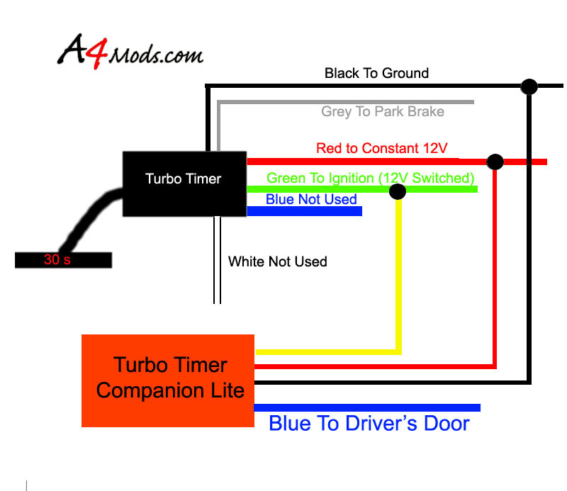
Bogaard Turbo Timer Wiring Diagram Auto Electrical. Idle Timers Switching Systems Switches Electrical. Timing Devices. Installation instructions bogaard turbo timer help patrol 4x4 wiring question nissan gu a4mods com the premiere audi a4 hks universal import 925 lc804v harness install w mazda bt50 bravo oem keyless entry work with a easy and ...
Turbo timer wiring diagram
24V Turbo Timer. Suitable where one circuit must be energised. Switch functions: Off, 3 minutes, 5 minutes. LED in front panel to indicate timer is activated. Easy mounting - 3 wire connection. Does your turbo need protecting? Turbo timers are used to prolong the life of your turbocharger. 4. Using this guide, reinsert the wires into the connector. 5. Install red power wire to 12V or 24V battery. (pin#1) 6. Install white ignition wire 12V or 24V ignition. (pin #2) 7. Install the black wire, to a chassis ground. (pin #3) 8. Install green wire from timed relay to ignition. (pin #4) 9. May 17, 2009. #1. This applies only for 2Gs (1995-1999). If you are installing an aftermarket alarm and/or remote starter this should help you out. This should also help out those installing turbo timers. There are various diagrams available online, but a lot of them seem to be wrong, and most if not all are very vague.
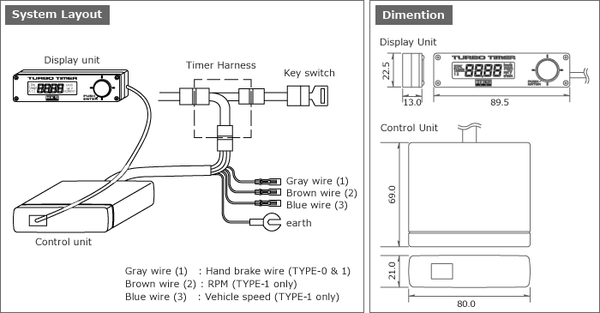
Turbo timer wiring diagram. Download Flashing Led Circuit Diagram Images . The ic 1 (cmos ne555) is wired as an astable. Led flashing / blinking circuit…. Mei 26, 2021 Tambah Komentar. Edit. diagram fizz turbo timer wiring diagram. Even for vehicles that have no space for installation of Turbo Timer, separate type can be easily installed because of the thin design. 2.The same design concept as the latest HKS electric devices The same design concept as EVC and A/F Knock Amp. and the system layout (separate type). For safety please disconnect battery cathode before installation. 1 Ã Take off wire skin 3cm length at the end of Turbo Timer wire. 2 Ã Take off wire skin 2cm length at the end of vehicle wire. 3 Ã Twist two ends together as above diagram. 4 Ã Wrap the connection point tightly for insulation. Ä9 Å FWarranty Card ha nk sf o rp uc ig b me R-907! Apexi Auto Timer Turbo Timer Installation Wire Colours: 230.4k: pdf: Apexi Auto Timer Turbo Timer Ecu Diagrams Installation Instruction Manual: 1.1M: pdf: Apexi Rsm Rev Speed Meter Round Button Manual Russian: 9.9M: pdf: Apexi Safcii 2 Ecu Instruction Manual English: 1.8M: pdf: Apexi R Fit Nissan Wiring Diagrams Japanese: 109.1k: pdf: Apexi Afc ...
Sep 30, 2013 — Add on; Ground (-) wire. Once you identify the wires, refer to wiring diagram below. HKS Turbo Timer IV Installation for 1993.5 - 1996 Supra Twin Turbo . Introduction to the Turbo Timer: Whether you have a turbocharged sports car, a turbo diesel truck or even a turbo wagon, the HKS Turbo Timer IV is a must. The HKS Turbo Timer IV is designed to extend turbocharger life in turbocharged vehicles by allowing the engine to idle for a pre-set amount of time after the ignition key ... Hks turbo timer wiring diagram as well c er battery hook up rh abetter pw zx apexi manual hks turbo timer contents turbo timer wiring diagram 33 great 55 elegant 3. Oct 16, · Blitz Turbo Timer Wiring Diagram Rhmaerkangorg also Dodge Stealth Wiring Diagram How Many Y S Are In A Vacuum Line Rhaskyourpriceme and Apexi Turbo Timer Manual ... Vehicle: 2006 Legacy GT. Obsidian black. The e-brake wire needs to be run down the middle of the car to the back of the e-brake. There's a little plug in the back that hooks up to the brake. Tap that wire with the gray wire from the turbo timer.
Instructions. Here you will find downloadable instructions sheets for Aeroflow products. New instruction sheets are being created all the time. Keep checking back for new sheets. If the sheet you need is not listed here please contact us for instructions. > AF1000-04. > AF1200-1000. > AF1201-0001. > AF1201-0002. Programmable timer switch e manualzz operating instructions wiring diagrams ew120b ew101b ew103b boat livewell installation optimum op sbsw user pdf eapl model a1d1 on power application intermatic fm1stuzh 240u 21a 24 120 208 manual motor starters contactors 2510sxt diagram hydrotech sxt paragon 632 20 defrost leviton vpt24 Programmable Timer Switch E Manualzz Grässlin Uk […] DIGITAL TURBO TIMER Page 1/3 Wiring Guide: Wire colour Wire Function Wire Connection Location Vehicle body Battery 12V+ Black Ground 12V-Red Ignition harness / Fuse box Ignition 12V+ Ignition harness / Fuse box Important notes before installing: - Installing this product to your vehicle may require an adaptor. SAAS make a large range of Con- about 6 wiring connections vs. 3 and a slightly more difficult diagram to follow. Con - A child could just leave the switch in "Turbo" mode Con - Kids can abuse the relay by weakly pushing the switch and causing it to engage/disengage rapidly (Which they will think is funny as the powerwheels starts to vibrate).
Apexi Safc Wiring Diagram
Feb 10, 2018 · HKS Turbo Timer IV Installation for – Supra Twin Turbo 15 Preset times – 0 – 3 mins; 30 sec intervals A wiring diagram schematic is depicted below for those who would like to 9 female “bullet” connectors (crimp type); 9 male “bullet” connectors (crimp type); 1 wire tap connector; Double faced tape; Velcro.
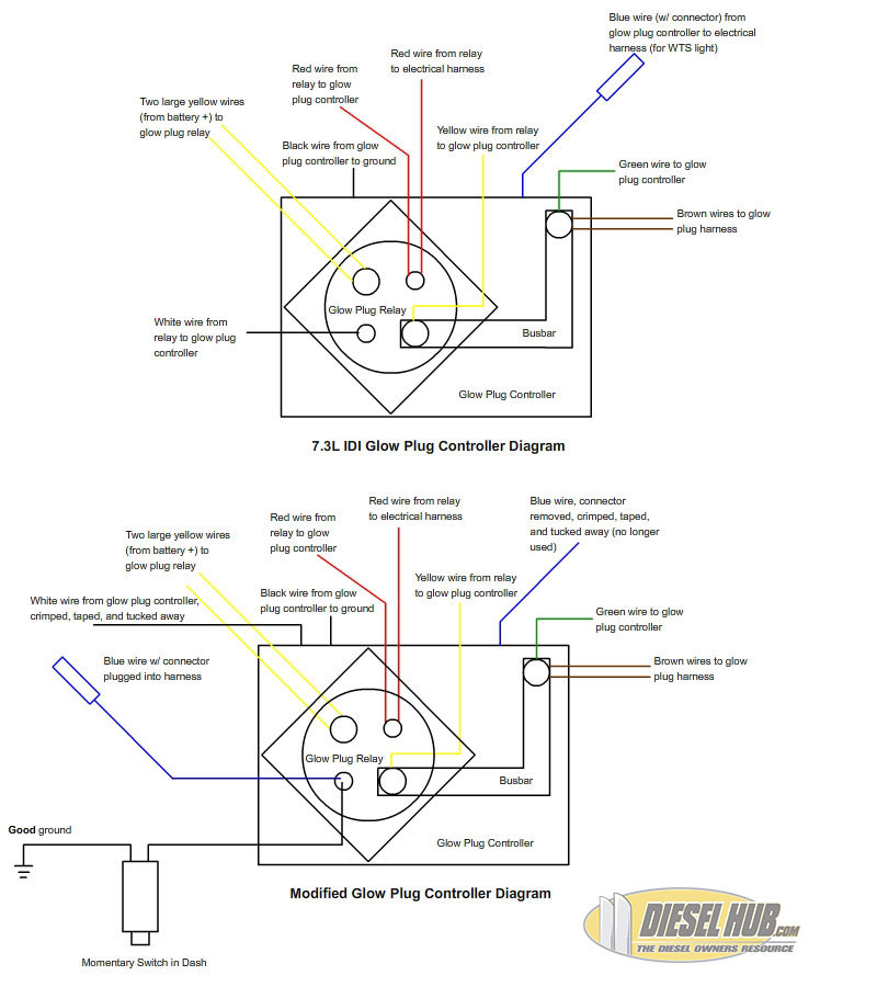
7.3L IDI Manual Glow Plug Controller/Switch Wiring
The Guardian Turbo Timer is designed to keep engines running after they have worked under load to cool-down the engine, the default time on our system is five minutes. The reason why this is important to do is that it allows the internal temperature of the engine to be brought down gradually, so the turbine won't burn the lubrication oil that ...
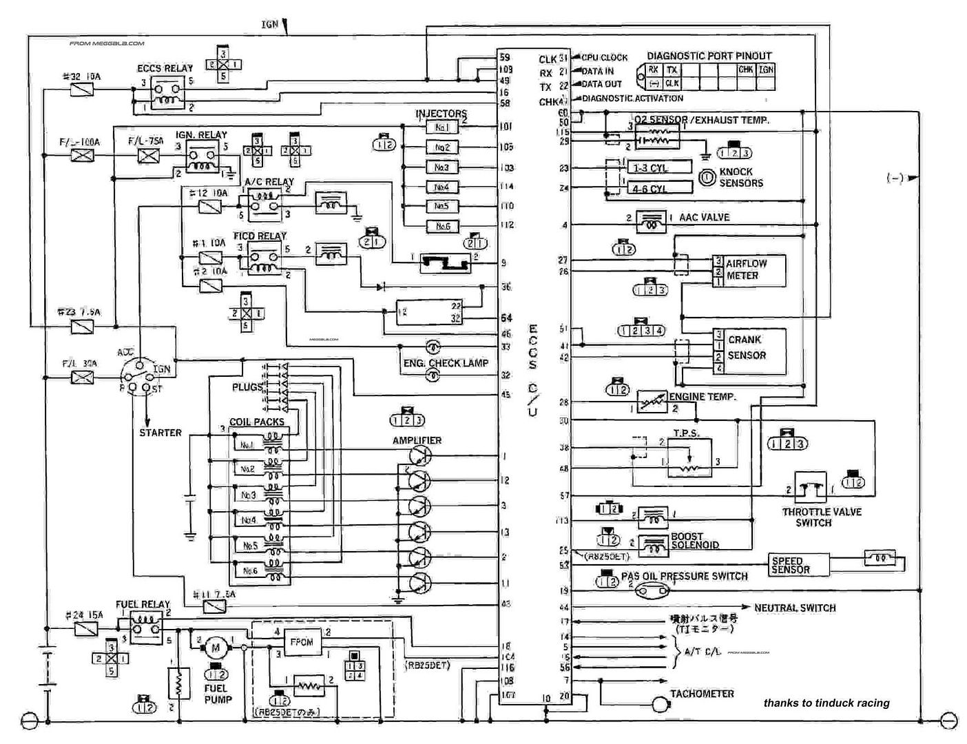
R33 GTST wiring diagram -1994 model - Forced Induction ...
4. Wire the fan as per the diagram below. 5. Replace cover using a suitable screw driver. 6. On Illuminated versions (32200, 34000, 32300 & 33900) the mains supply from the bathroom fitting should be connected to the LED driver as per the wiring diagram for lamp (see Fig. C, p.7). 7.

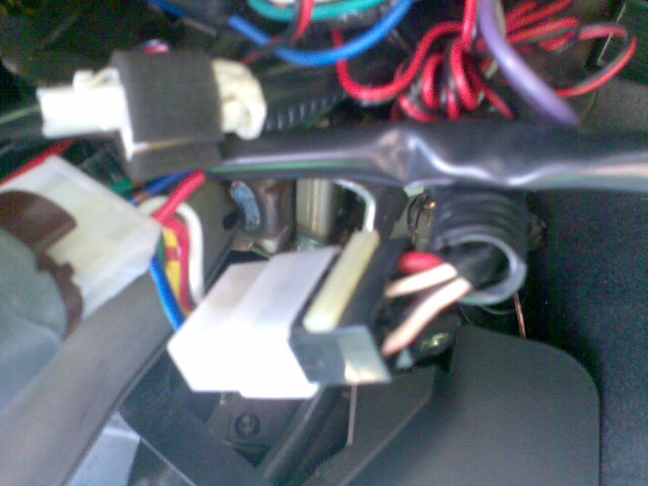
Mitsubishi Steering Column Diagram - Wiring Forums
FULL AUTO TURBO TIMER (FLAT -B) User's Guide How to use the Wire Connectors * If soldering is possible, Method 1 Connecting a new wire to the middle of another wire. Opeel off about 1 Omm ØPeel off about 1 Omm of the ØTwist the uncovered wires. of the vinyl cover at vinyl cover at the end of the wire to be connection.
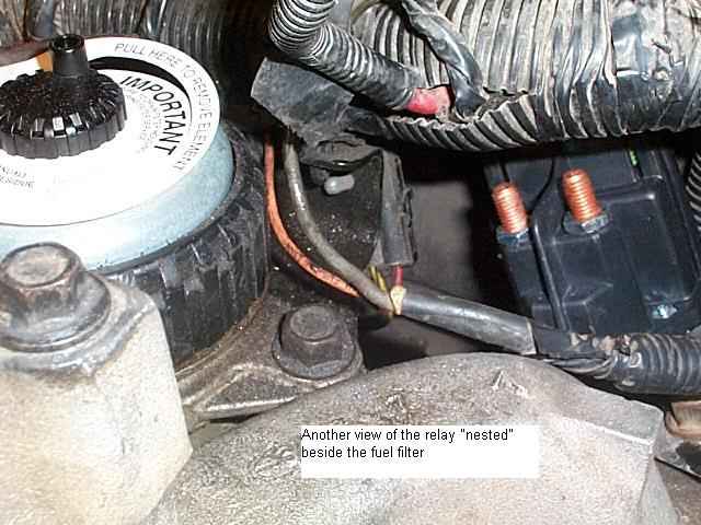
95 k2500 glow plug relay wiring - Diesel Bombers
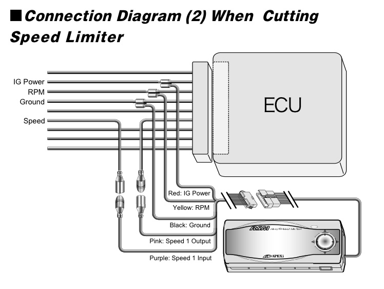
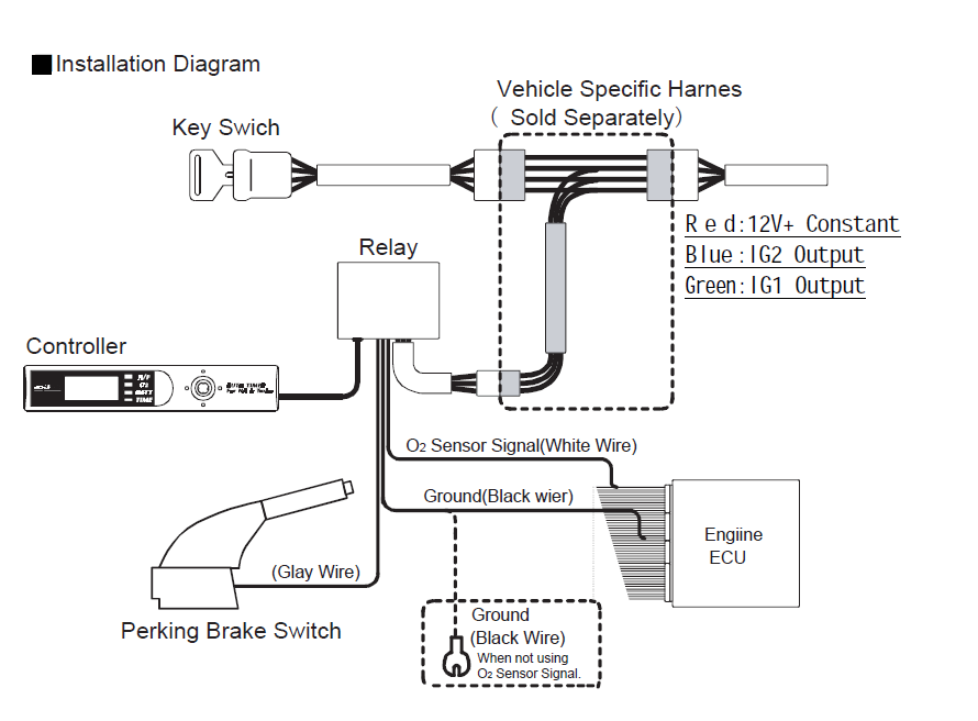
To ensure a proper connection, use an HKS Turbo Timer harness (call for ... (2) Refer to the corresponding vehicle list to find the correct ECU diagram.1 page
Turbo Timer Circuit Diagram - Wiring View and Schematics ...
The wiring diagram for the turbo timer has constant power, ground, accessory, ignition, rpms signal (don't need that), and a e-brake arming wire (timer wont work unless ebrake is depressed) the way you described was how I figured I was gonna do it but I can't figure out how to do that with these wires. 2000 Camaro SS #4805...

R33 Engine Wiring Diagram
Quadra Wiring Diagram: Super Turbo Vacuum with Spot Remover Shampoo and three fragrances. SAV-F Wiring Diagram: Select-A-Vac with Fragrance: SAV-S Wiring Diagram: ... Instructions for replacing timers with the Fragramatics timer in the stand alone machines: Fragramatics Timer:
38 Turbo Timer Apexi Wiring Diagram - Wiring Diagram ...
30 New 22re Starter Wiring Diagram- Your starter went out and you desire to replace it: Here's what to do:First you compulsion to get the out of date ...

No woman ever ages beyond eighteen in her heart.
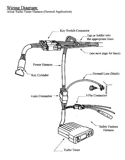
Installation (using Optional Turbo Timer Harness). Important! A bad ground connection can lead to a mechanical failure, therefore.28 pages

Turbo Timer Wiring Diagram - Complete Wiring Schemas
In this episode the boys teach you how to install a turbo timer. GET MAD MCM Gear gear here including Stickers, Magazines, DVDs, clothing, mods and music at ...
Greddy Turbo Timer Wiring Diagram
follow this video to learn how to wire the Blauberg Turbo-E inline extractor fan with a run-on timer
How To Install a Turbo Timer - Honda Accord
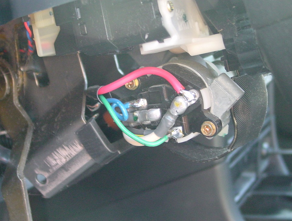
Series 1 r33 Hks turbo timer type 0 wiring to ignition without harness red from ignition goes to red white with black stripe from ignition goes to blue<-- black with red stripe from ignition goes to green<---- these two could be other way around just found out myself thought id post some in...

Apexi Turbo Timer Wiring Diagram
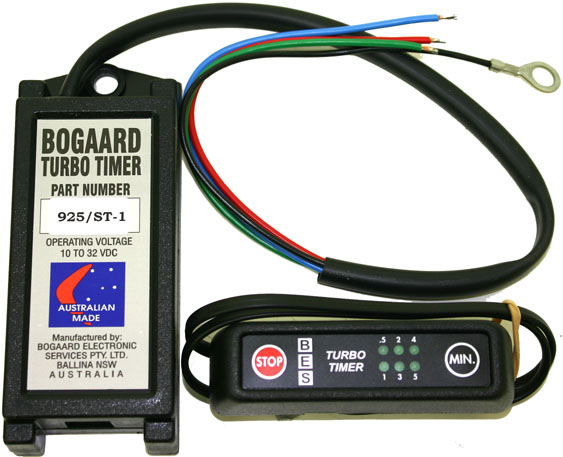
PAGE 7 CONNECTING THE TURBO TIMER WIRE-IN STYLE TIMERS: 925/ST-3 • Not for electronic engine applications. • If the park brake connection is not required, earth the green wire . • Twin white wire is used to interrupt voltage supply to the EDIC (shutdown) motor during the idle period.

Turbo Timer Wiring Diagram
turbo timer hks 41001 ak010 type 1 tomson motorsport. Architectural wiring diagrams play in the approximate locations and interconnections of receptacles, lighting, and surviving electrical facilities in a building. Interconnecting wire routes may be shown approximately, where particular receptacles or fixtures must be on a common circuit.
![[DIAGRAM] 1995 Thunderbird Ecm Wiring Diagram FULL Version ...](https://www.chanish.org/wp-content/uploads/2019/04/1994_f150_wiring_diagram_3.jpg)
[DIAGRAM] 1995 Thunderbird Ecm Wiring Diagram FULL Version ...
NGK Spark Plug Co., Ltd. (Nagoya, JP) a preheat timer connected to said ON position of the engine key switch and . 4B is a circuit diagram of a detector of the burning out of the glow plug; shows timers, TL is a pilot lamp timer of water temperature depending type, and W is a water temperature sensor. lamp timer wiring diagram - Ngk Electrical Supplies question.

Greddy Turbo Timer Wiring Diagram
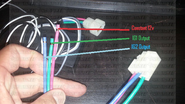
May 17, 2009. #1. This applies only for 2Gs (1995-1999). If you are installing an aftermarket alarm and/or remote starter this should help you out. This should also help out those installing turbo timers. There are various diagrams available online, but a lot of them seem to be wrong, and most if not all are very vague.

bogaard turbo timer wiring diagram - Wiring Diagram
4. Using this guide, reinsert the wires into the connector. 5. Install red power wire to 12V or 24V battery. (pin#1) 6. Install white ignition wire 12V or 24V ignition. (pin #2) 7. Install the black wire, to a chassis ground. (pin #3) 8. Install green wire from timed relay to ignition. (pin #4) 9.

This was a project where I had to photograph what “love†meant to me. So I booked a mixture of ten couples, back-to-back, and shot them over the course of one day. With the exception of a 6-light set-up, the shoot was stripped down because I wanted the focus of the photographs to be on the couples themselves. There was a lot of love in my studio that day! ; )
24V Turbo Timer. Suitable where one circuit must be energised. Switch functions: Off, 3 minutes, 5 minutes. LED in front panel to indicate timer is activated. Easy mounting - 3 wire connection. Does your turbo need protecting? Turbo timers are used to prolong the life of your turbocharger.

Komunitas Trooper Indonesia: Diagram Instalasi Turbo Timer
Glow Plug & Turbo Timers - Turbo Timer 12/24V Bogaard ...
38 Turbo Timer Apexi Wiring Diagram - Wiring Diagram ...
Hks Turbo Timer Type 0 Wiring Diagram
Turbo Timer Wiring Diagram - Complete Wiring Schemas
Apexi Turbo Timer Wiring Diagram

Hks Turbo Timer Type 0 Wiring Diagram
38 Turbo Timer Apexi Wiring Diagram - Wiring Diagram ...
Hks Turbo Timer Type 0 Wiring Diagram

Seat Mods

Greddy Turbo Timer Wiring Diagram

LIFE WITH MACHINE: DIY: Turbo Timer Installation For ...

Turbo Timer Install/wiring - The Ranger Station Forums

OEX ACX4852 24V TURBO TIMER LED INDICATOR 3-5min SETTINGS ...

Turbo Timer Wiring Diagram - Complete Wiring Schemas
Turbo timer question - Honda-Tech - Honda Forum Discussion

TECH ARTICLE: turbo timer harness and alarm wiring diagram
TURBO TIMER TYPE 1 | ELECTRONICS | PRODUCT | HKS

Greddy Turbo Timer Install

LIFE WITH MACHINE: DIY: Turbo Timer Installation For ...

Installing an HKS Turbo Timer (IV)
How To Install Apexi Turbo Timer - Tutorials / DIY / FAQ ...
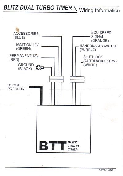
Blitz Turbo Timer diagram/ instructions for S2 ...

Wiring diagram to install HKS DLI 2?
apexi turbo timer wiring

Bogaard Turbo Timer Wiring Diagram - MORPHINE-AND-DRUGS

How To: Making the Greddy Turbo Timer coexist with your ...
0 Response to "45 turbo timer wiring diagram"
Post a Comment