45 wiring diagram identify
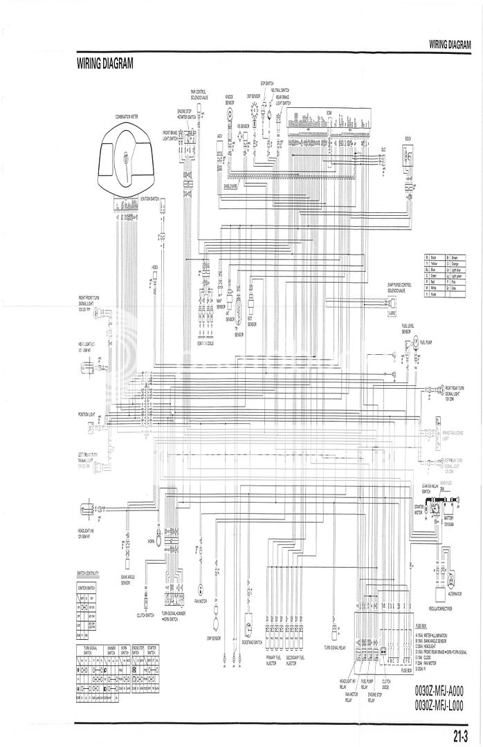
Wiring diagrams , also called connection diagrams, however, do show how equipment is laid out and the connections between them. A wiring diagram shows the relative layout of the components and the wire connections between them. All circuits in the diagrams use an alphanumeric code to identify the wire and its function (Fig. 3). To identify which circuit code applies to a system; refer to the Circuit Identification Code Chart. This chart shows the main circuits only and does not show the secondary codes that may apply to some models. H-Open Figure 2 - Wire Color Code ...
Switch Wiring Diagrams A single switch provides switching from one location only. "Single-Pole" may sound simple, but there are different ways to wire a Single-Pole Switch. The power can come from either the switch box or the fixture box and a set of electrical switch wiring diagrams will explain each of these scenarios to you clearly.

Wiring diagram identify
3Way Switch Wiring Diagrams #1, #2 and #3 The key to three way switch wiring depends on two main factors. These wiring diagrams help you identify the power feed and the switch leg leading to the fixture. 3 Way Switch Wiring Diagram Part 2 3Way Switch Wiring Diagrams #4, #5 and #6 Continuing on with wiring three way switches, these next three ... The components within the circuit are represented by a series of pictorials and these accurately resemble the components within the system so they can be easily identified. While the horizontal and vertical lines of a schematic show the circuit's flow, lines in a wiring diagram instead represent the physical wiring of the circuit. 3. Pictorial 27.10.2019 · starter diagram wiring yer 5 3 mustang guys help ford solenoid 0 sas 4201 12 volt solenoid wiring diagram wiring diagram name. A set of wiring diagrams may be required by the electrical inspection authority to take on membership of …
Wiring diagram identify. Visio Wiring Diagram- wiring diagram is a simplified up to standard pictorial representation of an electrical circuit.It shows the components of the circuit as simplified shapes, and the capacity and signal links amid the devices. A wiring diagram usually gives assistance virtually the relative slant and conformity of devices and terminals on the devices, to incite in building or servicing ... 2. Describe the meaning of the "G-W" in diagram component R. 3. Describe the meaning of the "2" in diagram component S. 4. Describe the meaning of the "S/D" in diagram component T. 5. Describe and identify the diagram component U. 6. Describe and identify the diagram component V. 7. Describe and identify the diagram component W. 8. shown on the wiring diagram in the vehicle harness or at the connectors is a lot easier. System Circuit Diagrams The entire EWD is built around the System Circuit Diagram. Every number, letter, shape, and shading on the diagram tells you information that can help you to locate or identify components on the car faster. Section I System Circuit Diagrams Advantages. Using … Wiring diagrams are mainly used when trying to show the connection system in a circuit. It is majorly used by building planners, architects, and electricians to present the wiring connections in a building, a room, or even a simple device. They can be accommodating when determining a fault in the connections, installing new wires and devices, locating electrical outlets, etc.
The lesson presents information how to identify components, equipment, wires and cables on a wiring diagram. It also explains how to relate a wiring diagram to the installed hardware and how to use diagrams for maintenance and troubleshooting problems. Objectives Identify components in a wiring diagram. 02.12.2019 · If you can follow a panel wiring diagram, you will be able to find the root cause of any problem in a panel! Learn how to follow an electrical panel wiring diagram below. Let’s go back and have a look at the control panel, and try and figure out some of the connections by following a wiring diagram. As I’ve mentioned in the previous articles, this is a control panel … 26.07.2020 · Print the wiring diagram off plus use highlighters to trace the signal. When you make use of your finger or perhaps the actual circuit with your eyes, it is easy to mistrace the circuit. 1 trick that We 2 to printing a similar wiring plan off twice. Upon one, I’ll trace the current movement, how it operates, and that exhibits me what parts of the signal I need to be able to … A the connecting leads or pins of a component in a schematic diagram can be identified using letters or abreviations. For example, the connecting leads of a ...
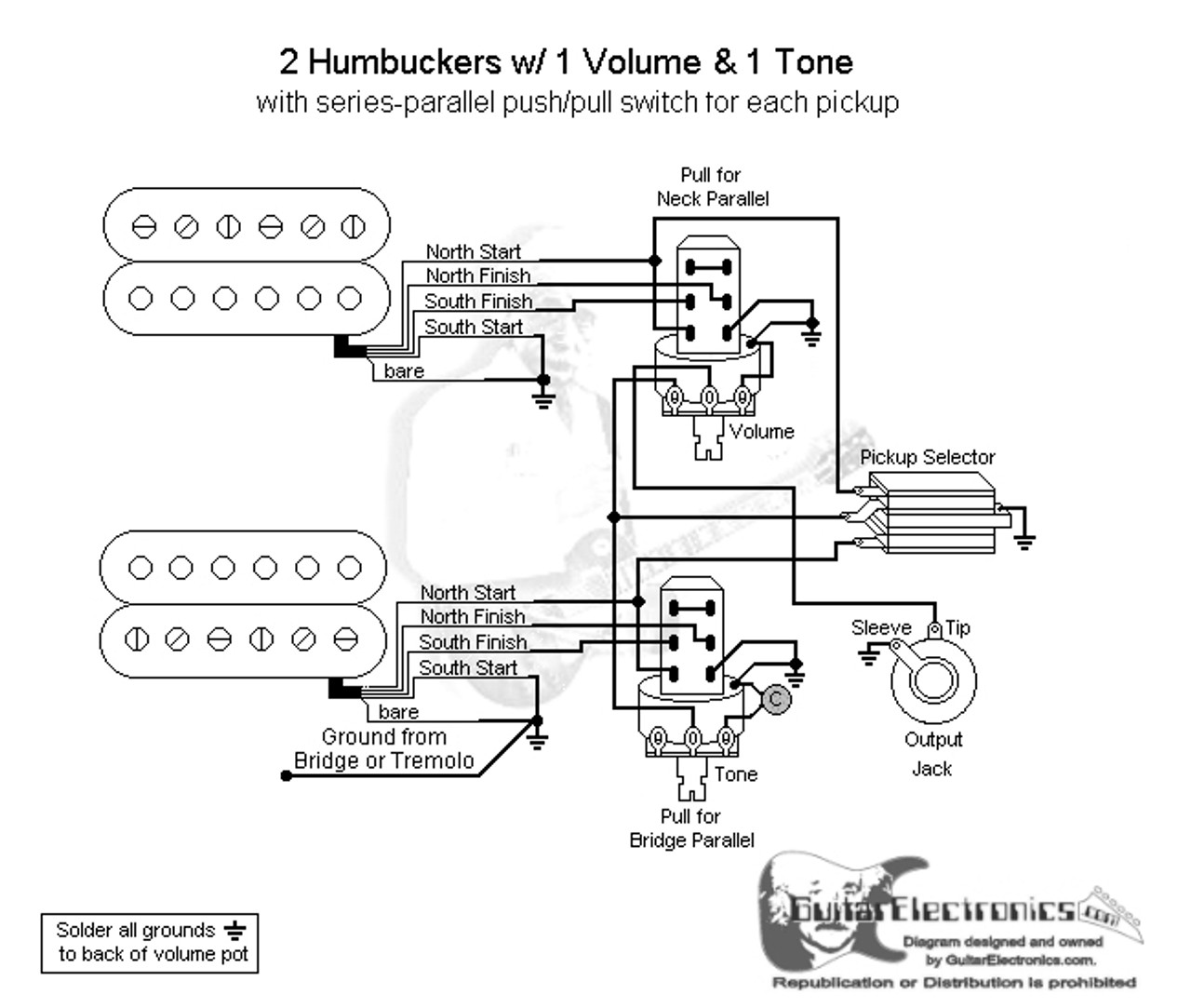
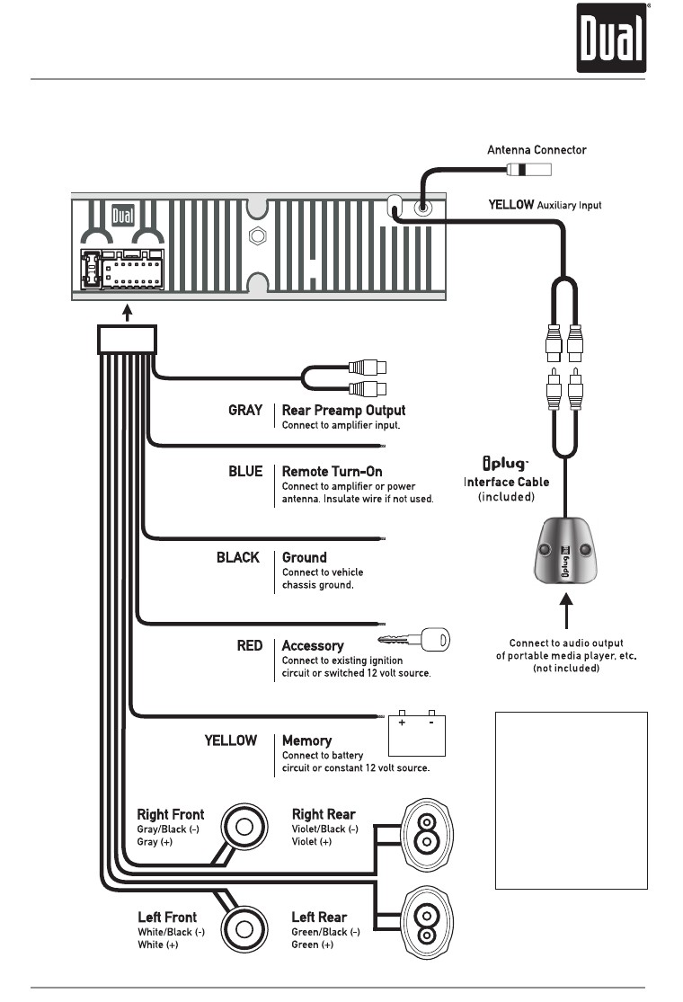
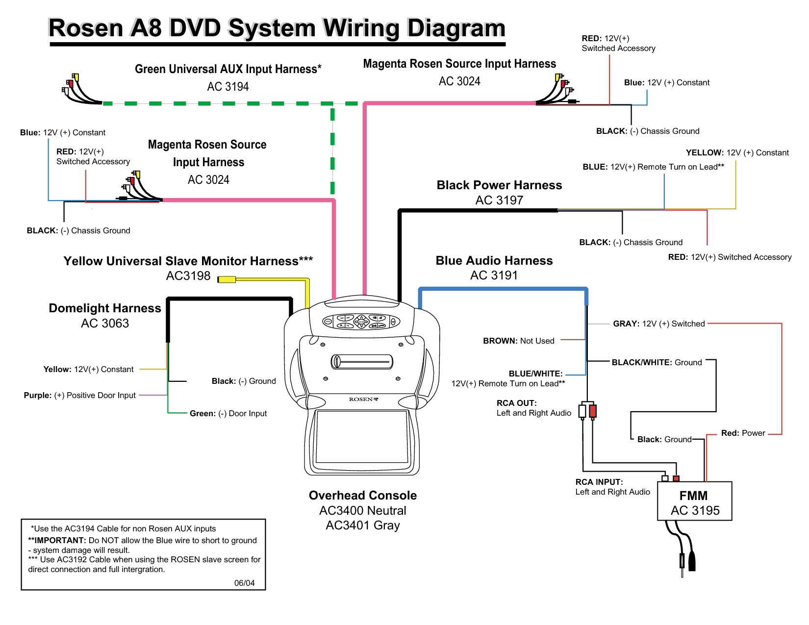
DaimlerChrysler Corporation wiring diagrams are designed to provide ... Each wire shown in the diagrams contains a code which identifies the main circuit, ...19 pages A wiring diagram for parts of an electric guitar, showing semi-pictorial representation of devices arranged in roughly the same locations they would have in the guitar. An automotive wiring diagram, showing useful information such as crimp connection locations and wire colors. These details may not be so easily found on a more schematic drawing. Typical Trailer Wiring Diagram and Schematic. The 2 above wire diagrams fit the needs of most trailers. The first image shows a single axle trailer, and the second, wiring for Tandem Axles. Only the (blue) brake and (white) ground wires are different. You can expand the same conditions for more axles. Light switch wiring diagram depicted here shows the power from the circuit breaker panel going to a wall switch and then continues to a ceiling light with a three conductor cable. From the ceiling box an electrical receptacle outlet is fed power. The diagram above shows a two conductor cable from the circuit breaker panel going to a wall switch ...
2013 Road Glide Stereo Wiring Diagram : 1963 Dodge Dart ...
The wiring diagrams on this page make use of one or more 4 way switches located between two 3 way switches to control lights from three or more points. Several diagrams are included here that can be used to map 4 way and 3 way lighting circuits depending on the location of the source in relation to the switches and lights.
3 Humbucker 5-Way 2 Push Pull Wiring Diagram - Database ...
Schematic Reading Tips. Identify Blocks. Truly expansive schematics should be split into functional blocks. There might be a section for power input and voltage ...

Image from page 986 of "Hardware merchandising September-December 1922" (1922)
TERMINAL MARKINGS AND INTERNAL WIRING DIAGRAMS SINGLE PHASE AND POLYPHASE MOTORS MEETING NEMA STANDARDS See Fig. 2-11 in which vector 1 is 120 degrees in advance of vector 2 and the phase sequence is 1, 2, 3. (See MG 1-2.21.)* MG 1-2.24 Direction Of Rotation

4 Pin Rectifier Wiring Diagram - 35 Amp 3-Phase Bridge ...
View Identify the components in the wiring diagram.docx from MECHANICAL ENGMECHANI at University of Toronto. Identify the components in the wiring diagram. What is the digital multimeter used
Alpine Radio Wiring Diagram - Database | Wiring Collection
Wiring diagrams use simplified symbols to represent switches, lights, outlets, etc. Here is the wiring symbol legend, which is a detailed documentation of common symbols that are used in wiring diagrams, home wiring plans, and electrical wiring blueprints.

1963 Cadillac Series 62 Color Wiring Diagram
Complete with a color coded trailer wiring diagram for each plug type, including a 7 pin trailer wiring diagram, this guide walks through various trailer wiring installation solution, including custom wiring, splice-in wiring and replacement wiring. If your vehicle is not equipped with a working trailer wiring harness, there are a number of different solutions to provide the perfect fit for ...

Image from page 919 of "Electric railway journal" (1908)
A car wiring diagram is a map. To read it, identify the circuit in question and starting at its power source, follow it to the ground. Use the legend to understand what each symbol on the circuit means. I'm an auto technician for over twenty years, I've always loved the electrical side of auto repair.

Ge Ecm X13 Motor Wiring Diagram - Collection - Wiring ...
Wiring a Telephone Jack After installing the Cat 3 - 3 pair phone wire I am ready to install the wall jack. You will have a wide variety of telephone jacks to choose from but the wiring for a single line phone service will be standard.

Pilot Light Switch Wiring Diagram - Pilot Switch Wiring ...
Wiring Diagram for a Split Outlet This diagram illustrates the wiring for a split receptacle with the top half controlled by SW1 and the bottom half always hot. The receptacle is split by breaking the connecting tab between the two, brass colored terminals. The tab between the neutral, silver terminals should remain intact.

Identify diagram: 1985 Chevrolet El Camino v8 Wiring Diagram
To read a wiring diagram, you should know different symbols used, such as the main symbols, lines, and the various connections. The standard or fundamental elements used in a wiring diagram include power supply, ground, wire and connection, switches, output devices, logic gate, resistors, light, etc.

Typical Computer Headset Wiring Diagram - Barkingmode.
Wire diagrams use wire color codes to identify the color of wire being used to connect different electrical components within the circuit. Some wire colors are ...Wire color: Wire FunctionWH/BL=White with black markings: Hot wire ca...Others (use diagram key): MultifunctionalWH=White: Neutral wire carrying current at zero ...

Windshield Wiper Motor Wiring Diagram Ford Pictures ...
A wiring diagram may include the wirings of a vehicle. For example, how the horns are powered and connected to the controller on your steering wheel. Or an electrical wiring diagram can be a 200-page document including all the electrical wirings of an electrical control panel in a huge factory or plant.
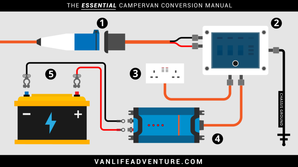
Campervan Wiring Diagram Uk Collection
04.04.2019 · Jayco Trailer Wiring Diagram. Variety of jayco trailer wiring diagram. A wiring diagram is a streamlined standard pictorial depiction of an electrical circuit. It shows the elements of the circuit as streamlined shapes, and the power as well as signal connections in between the devices. A wiring diagram typically provides information regarding the family…

Kohler Ignition Switch Wiring Diagram - Collection ...
Trailer Wiring Diagram. Trailer Wiring Diagram. Not sure which wires attach to what on your trailer connectors? Does one of your turn signals not work and you’re not sure which wire to inspect? Check out or trailer wiring diagrams for a quick reference on trailer wiring. The below information is for reference and is commonly used throughout the industry, but can vary …
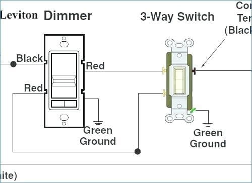
Leviton Dimmer Switch Wiring Diagram : Leviton 3 Way ...
Wiring Diagrams. Electrical wiring diagrams are included in most aircraft service manuals and specify information, such as the size of the wire and type of terminals to be used for a particular application. Furthermore, wiring diagrams typically identify each component within a system by its part number and its serial number, including any ...
Honda Cbr 600 Wiring Diagram Pics - Wiring Diagram Sample
Ground source, are numbered and identified in the wiring diagram. Conductors and components. Between the central/relay panel and the.86 pages

1980 Honda Cb650 Wiring Diagram Collection - Wiring ...
HOW TO READ THE WIRING DIAGRAMS - Wire Colour Codes A-9 WIRE COLOUR CODES Wire colours are identified by the follow colour codes. Code Wire colour Code Wire colour B Black P Pink BR Brown R Red G Green SB Sky blue GR Gray SI Silver L Blue V Violet LG Light green W White O Orange Y Yellow If a cable has two colours, the first of the two colour code

Help!- Can You Identify These Ignition Switch Terminals ...
The ones in the wiring diagram above are correct. This is the same for the jumper block OUT7 - OUT9 that provides power to these connectors respectively (see below). Caution! On v0.5 boards, do not connect anything to the OUT pin of the IO_5 connector, because on the prototype boards this pin is used to signal to the Raspberry Pi. The IO_5_OUT pin will be available on later …

25+ Citroen C4 Grand Picasso Wiring Diagram
Now look at the lower portion of the wiring diagram in Fig.18 and locate the relay coils "IFR" and "C1" on lines 52 and 57. B- Numbers on Right hand side of the diagram: In Fig.19C , note that there are small numbers along the right hand side of the diagram as well.

1999 Ford F250 Super Duty Wiring Diagram Pics | Wiring ...
The wiring diagrams were then compared to the circuit designs and common errors in the circuit diagrams, the wiring diagrams as well as subsequent examination responses to related questions were recorded and categorised according to alternative models of electric current identified in the literature.
Viper 5701 Installation Wiring Diagram
What is a Wiring Diagram? A wiring diagram is a simple visual representation of the physical connections and physical layout of an electrical system or circuit. It shows how the electrical wires are interconnected and can also show where fixtures and components may be connected to the system. When and How to Use a Wiring Diagram

1995 Toyota 4runner Wiring Diagram - Wiring Schema
Electrician Circuit Drawings and Wiring Diagrams Youth Explore Trades Skills 3 Pictorial diagram: a diagram that represents the elements of a system using abstract, graphic drawings or realistic pictures. Schematic diagram: a diagram that uses lines to represent the wires and symbols to represent components.

Caravan & Trailer 13 pin euro wiring chart from Western ...
Find Schematics, Wiring Diagrams, Etc. for Everyday Electronic Devices: Introduction If you've ever found yourself taking apart various electronics to build ...10 Sept 2009

2015 Hyundai Sonata Radio Wiring Diagram Pics - Wiring ...
27.10.2019 · starter diagram wiring yer 5 3 mustang guys help ford solenoid 0 sas 4201 12 volt solenoid wiring diagram wiring diagram name. A set of wiring diagrams may be required by the electrical inspection authority to take on membership of …

Identify diagram: 1998 Ford f800 Wiring Diagram
The components within the circuit are represented by a series of pictorials and these accurately resemble the components within the system so they can be easily identified. While the horizontal and vertical lines of a schematic show the circuit's flow, lines in a wiring diagram instead represent the physical wiring of the circuit. 3. Pictorial
1995 Mitsubishi Eclipse Stereo Wiring Diagram : Mitsubishi ...
3Way Switch Wiring Diagrams #1, #2 and #3 The key to three way switch wiring depends on two main factors. These wiring diagrams help you identify the power feed and the switch leg leading to the fixture. 3 Way Switch Wiring Diagram Part 2 3Way Switch Wiring Diagrams #4, #5 and #6 Continuing on with wiring three way switches, these next three ...

Boat Trailer Lights Wiring Diagram : 7 pin trailer plug ...
Viper 5701 Installation Wiring Diagram

Image from page 153 of "The Street railway journal" (1884)
place to be

Closeup of skeleton hand model

Image from page 245 of "The Street railway journal" (1884)

Image from page 435 of "Cyclopedia of applied electricity : a general reference work on direct-current generators and motors, storage batteries, electrochemistry, welding, electric wiring, meters, electric lighting, electric railways, power stations, swit

Ford Focus ST1 Stereo - Page 5

Wiring Diagram For Alternator With Internal Regulator Database

Ignition Coil Wiring Diagram - Ignition Coil Diagram Mazda ...

Schematic 3 Speed Fan Motor Wiring Diagram Database
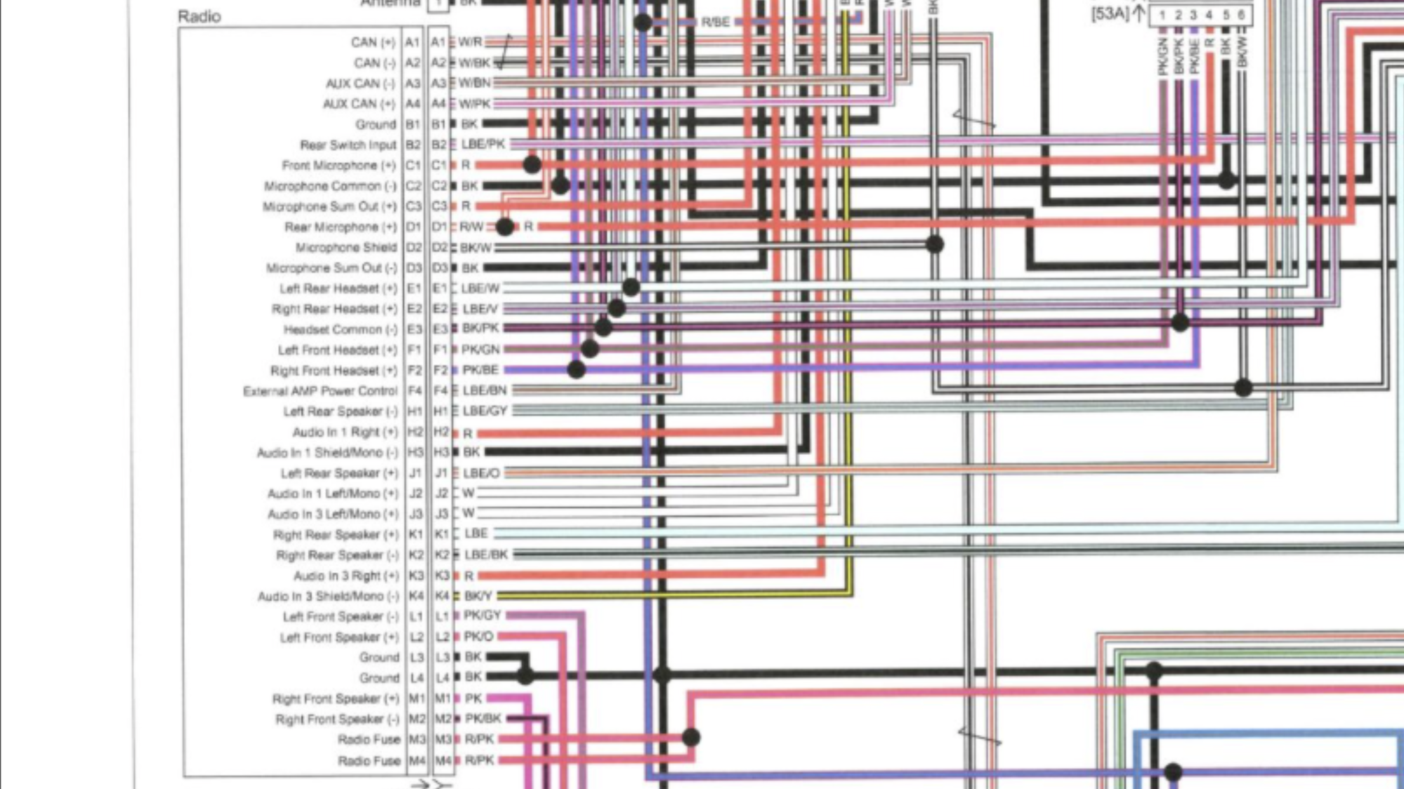
2016 Audio Wiring Schematic - Harley Davidson Forums

Crown Victoria Lcm Wiring Diagram

1988 Honda Fourtrax 300 Wiring Diagram Images | Wiring ...

Image from page 264 of "Gleanings in bee culture" (1874)
2002 Honda Cbr 600 F4I Wiring Diagram Collection | Wiring ...

Monochrome, Power Lines, Winlaton Mill, Tyne & Wear, England.

Electric Winch Wiring Diagram For Your Needs

2001 Chevy Silverado Power Window Wiring Diagram ...
0 Response to "45 wiring diagram identify"
Post a Comment