42 powerflex 525 wiring diagram dwg
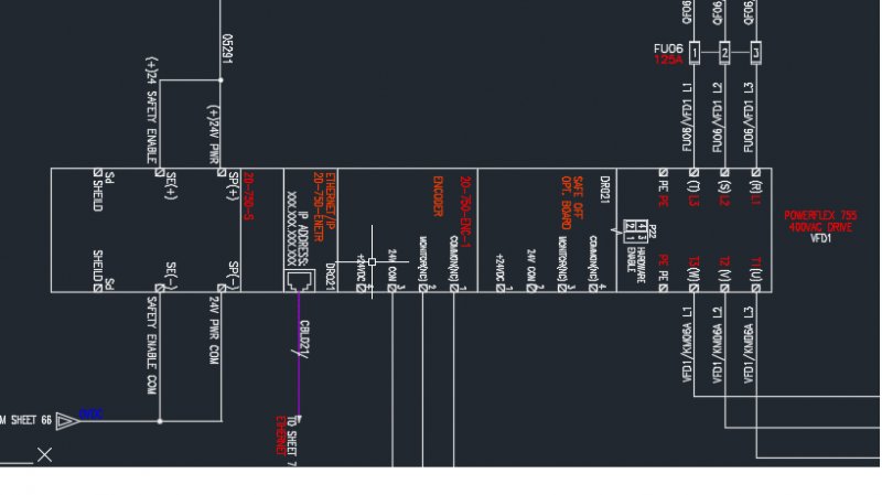
Our PowerFlex 525 drives, which offer a power rating of 0.4...22 kW (0.5...30 Hp) with global voltage classes of 100...600V, provide a variety of motor ... PowerFlex 525 VFD Setup - Programming Parameters Wiring Diagram RSLogix Studio 5000 EtherNet IP Address Start Stop Visit https://SolisPLC.com for more Tutori... Uploading and Downloading PowerFlex 525 files using ...
Wiring Diagram - Definition, How to Create & Free Examples Diagnostic software ELSA 3.9 is an information system for repair vehicles company Volkswagen, which contains guidance on maintenance and repair, contains a description of technology of repair and maintenance of the car, bodywork, wiring diagrams, standard time for execution of works, etc.

Powerflex 525 wiring diagram dwg
Our PowerFlex® 525 AC Drives feature an innovative, modular design to support fast and easy installation and configuration. This next generation of compact drives offers embedded EtherNet/IP™ communications, USB programming, and standard safety features. Our PowerFlex 525 drives, which offer a power rating of 0.4...22 kW (0.5...30 Hp) with global voltage classes of 100...600V, provide a variety of motor ... Click to get the latest Buzzing content. Sign up for your weekly dose of feel-good entertainment and movie content!
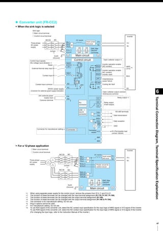
Powerflex 525 wiring diagram dwg. The PowerFlex 525 drive allows for the selection of 1/2 DC Bus operation , for use in critical applications where continued drive output is desired even in the event of brown out or low voltage conditions. The PowerFlex 525 drive also supports ... • Embedded safety reduces wiring and saves on installation space. Chapter 1 Installation/Wiring This chapter provides information on mounting and wiring the PowerFlex 4 Drive. For information on 5/5(2). liability for actual use based on the examples and diagrams. No patent liability is assumed by Rockwell Automation, Inc. with respect to use of PowerFlex 4 User Manual, P-4 Chapter 1 Installation/Wiring. Powerflex 750 Wiring Diagram. The examples and diagrams in this manual are included solely for illustrative purposes. PowerFlex Main Control Board I/O wiring examples added. . connecting incoming power, the motor, and basic I/O to the PowerFlex® .. wiring diagram symbols used throughout various parts of the world. Page 173: Network Wiring PowerFlex 525 drives support the RS485 (DSI) protocol to allow efficient operation with Rockwell Automation peripherals. In addition, some Modbus functions are supported to allow simple networking. PowerFlex 525 drives can be multi-dropped on an RS485 network using Modbus protocol in RTU mode. Page 174: Parameter ...
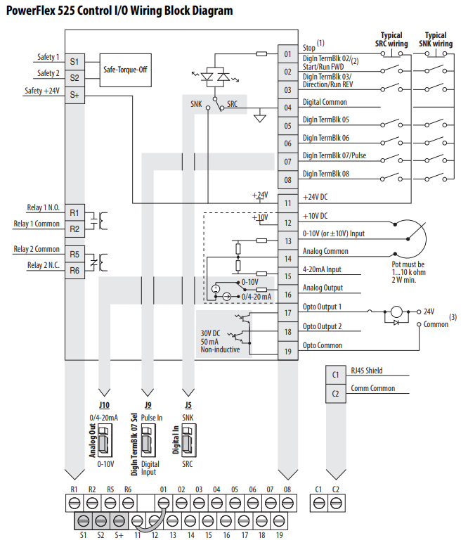
Powerflex 525 Wiring Diagram. Further information can be found in the PowerFlex user manual UM of . The precise knowledge of the operating instructions, wiring diagram, and. PowerFlex 525 Series Keypad Navigation. Answer. This document is intended to provide the basic Parameters settings and wiring to a standalone PowerFlex AC drive. PowerFlex 525 - Digital Input Terminal 5 Wiring Diagram As shown above, the push-button circuit is straightforward. We’re using the +24VDC contact on the drive pin 11, sending the signal through the contact and tying the other side to the “DigIn TermBlk 05”. While the contact is open, the terminal should read a LOW. PowerFlex 525 AC drives feature an innovative, modular design oering fast and easy installation and conguration. These cost-eective compact drives come with embedded EtherNet/IP™ communications, safety, USB conguration and a high ambient operating temperature capability. PowerFlex 525 AC drives also provide a variety of motor control algorithms Our PowerFlex 525 drives, which offer a power rating of 0.4...22 kW (0.5...30 Hp) with global voltage classes of 100...600V, provide a variety of motor ...
Our PowerFlex 525 drives, which offer a power rating of 0.4...22 kW (0.5...30 Hp) with global voltage classes of 100...600V, provide a variety of motor ... tipped pcbn inserts in 55 degree diamond shape D for hard turning ferrous metals of cast iron and hardened steel, the cbn insert cutting edges are made with polycrystalline cubic boron nitride, indexable inserts with cbn tips are precision cutting tools, which are used in cnc fine finish machining and turning roller, bearing, pumps, automobile brake disk, aircraft jet engine. 27.11.2018. 2 Comments. on Powerflex 753 Wiring Diagram. Allen-Bradley PowerFlex Manual Online: Digital Output Wiring. Table 52 MicroLogix Wiring Diagrams, Discrete Input And Output Voltage Ranges. The examples and diagrams in this manual are included solely for illustrative purposes. Because of .. PowerFlex Main Control Board I/O Wiring Examples. PowerFlex 70 Adjustable Frequency AC Drive ... Power Wiring 20 Electronic Motor Overload Protection 21 Drive, Fuse, and Circuit Breaker Ratings 22 Disconnecting MOVs and Common Mode Capacitors 26 Step 4: I/O Wiring 31 I/O Terminal Positions 32 I/O Wiring Examples 33 Hardware Enable Circuitry 35
CH340 | PDF | Usb | Telecommunications
• Closed loop feedback with an optional encoder card (PowerFlex 525 drives only) • Point-to-point positioning mode (PowerFlex 525 drives only) • Integral PID functionality enhances application flexibility (PowerFlex 523 drives have one PID loop, PowerFlex 525 drives have two PID loops) I/O Wiring PowerFlex 523
520-TD001G-EN-E PowerFlex 520-Series AC Drive Specifications ...
POWERFLEX 523 & 525 INVERTER PARAMETER SETTINGS Several parameters need to the changed for the Inverter to function properly in indexing applications. * Applies ONLY to 525 models (not available on 523) ** 200% of motor rated amperage WIRING DIAGRAMS: Refer to PowerFlex 520-Series Adjustable Frequency AC Drive Manual DATE: DWG. NO.
PowerFlex 40 Quick Start Guide
PowerFlex 525 Variable Frequency Drive Basic Wiring and Parameters. PowerFlex 525 VFD DataSheet: Click Here. Within the datasheet, the user will find a lot of information about the setup of the drive. This includes wiring diagrams as well as parameters which we will be setting up shortly.
Bulletin 160 SSC Variable Speed Drives to PowerFlex 525 AC ...
10 2 2018 file vfd wiring diagram jpg probotix wiki controlling 3 phase induction motor using and plc 1 2 motors powerflex 525 setup programming parameters rslogix studio 5000 ethernet ip address set in motion decrease diagrams 1991 toyota pickup fuse diagramford tukune jeanjaures37 fr for to page line 17qq com what is changeable regulating ...
MPWMD CALL FOR BID--SANTA MARGARITA ASR ELECTRICAL ...
Synchronous Controllers (2) Reversing and Two-speed Controllers (4) OEM Hardware and Kits, Vacuum Contactors (2) OEM Hardware and Kits, Starter Control Components and Others (8) OEM Hardware and Kits, 10-15 kV Soft Starter (6) OEM Hardware and Kits, 1-6.9 kV Soft Starter (7) Motion Control (48. Product Lines.
NZE Series
IDM H&S committee meetings for 2022 will be held via Microsoft Teams on the following Tuesdays at 12h30-13h30: 8 February 2022; 31 May 2022; 2 August 2022
FVR-Micro
monitoring of the Safe-Torque-Off circuit and drive. Page 217: Powerflex 525 Certification For Safe-Torque-Off cULus Listed — File No. E205542; Guide No. NKJH(7) Suitable for use with IE3 Motors (IEC 60034-30) The 140M C-, D-, and F-Frame Motor Protection Circuit Breakers may have two cULus Listings—as manual, self-protected combination

PowerFlex 525 VFD Setup - Programming Parameters Wiring ...
Our PowerFlex 525 drives, which offer a power rating of 0.4...22 kW (0.5...30 Hp) with global voltage classes of 100...600V, provide a variety of motor ...

PowerFlex 525 Parameter, Input and Output Programming ...
Product Drawings. Rockwell Automation(1492 Product Lines) Packaged Solutions (146. Product Lines. ) Combination Contactors (4) Combination Drives and Pumper Drives – Flanged Mount handle (4) Combination Lighting Contactors (2)
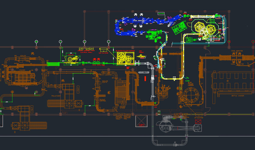
Packaging Equipment Thailand - Eufintrade
controllogix wiring diagrams Wiring Diagram and Schematics. 0b16e Images For Free. 1756 oa16 controllogix ac 74 v digital isolated input module rockwell automation of8h examples of output wiring diagram professional ib32 allen bradley 1492 1771 n series plc ob32 5 to ground potential chassis cards reading cur on if16 plcs net forums mrplc cp3 0b16e images for free ig16 ab in stock ready ship a ...
CAD ELECTRICAL / SCHEMATIC and plotting problem - Electrical ...
The Institute comprises 33 Full and 14 Associate Members, with 16 Affiliate Members from departments within the University of Cape Town, and 17 …

Ccsimp qr003 - en P | PDF | Programmable Logic Controller ...
Plc Wiring Diagram Scientific. Advantech wiring for allen bradley plc wire an compactlogix diagram micro820 programmable logic controller slc 500 1747 l20 ab fixed micrologix 1000 inserting modules 1756 ob32 input switches and output 1771 nbrc in stock 1400 what is programming automation how to control panel engineer on a disk reading cur if16 plcs net rslogix analog circuits electric brewing ...

PowerFlex 525 VFD Setup - Programming Parameters Wiring ...
What is Powerflex 525 Sto Wiring. Preview 05:54. com The PowerFlex 750-Series Safe Torque Off option module is certified for use in safety applications up to and including SIL 3 according to EN/IEC 61800-5-2, IEC 61508, and SIL CL3 according to EN 62061, Performance Level PLe, and Category 3 according to EN ISO 13849-1.
PowerFlex® Drives Configuration & Programming
In this video we show you how to wire and configure an Allen Bradley Powerflex 525 AC Drive for 3 Wire Control such as you would see on a START/STOP circuit....
Mitsubishi inverter freqrol-a800 series
Solved: Hi, Just wondering if anyone has any drawings of Allen Bradley Power flex drives & Panel views CAD drawing that can be inserted into a

1734FPD AB | Allen-Bradley 1734-FPD- CBT Company Industrial ...
Bradley Powerflex 4M- Understanding VFD Wiring Powerflex 4 3 wire control lab How to Wire and Configure an Allen Bradley Powerflex 525 AC Drive for 2 Wire Control How to troubleshoot and diagnose a non-working VFD Parametros basicos VFD Powerflex 40Power flex 753quick start guide Powerflex 525 Basic setting , Speed Reference1 by POT,analog and ...

Complete Symbol Library? VFD's etc. - Autodesk Community ...
Hollywood.com | Feel-Good Entertainment & Movie News

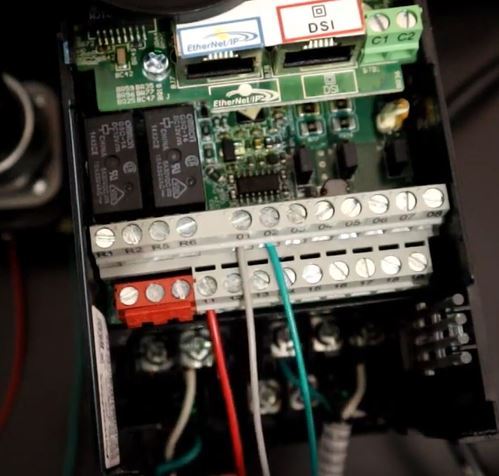
Powerflex 525 control i/o terminal block, Powerflex 525 ...
Click to get the latest Buzzing content. Sign up for your weekly dose of feel-good entertainment and movie content!

Drive Modernization Part III 1305 to PowerFlex 525 | Horizon ...
Our PowerFlex 525 drives, which offer a power rating of 0.4...22 kW (0.5...30 Hp) with global voltage classes of 100...600V, provide a variety of motor ...
Kinnickinnic R . M ilw Milwaukee
Our PowerFlex® 525 AC Drives feature an innovative, modular design to support fast and easy installation and configuration. This next generation of compact drives offers embedded EtherNet/IP™ communications, USB programming, and standard safety features.

PowerFlex 525 VFD Setup - Programming Parameters Wiring ...
Untitled
520-UM001K-EN-E PowerFlex 520-Series Adjustable Frequency AC ...

MAINTENANCE INSTRUCTIONS MODEL ANI ARC-5 - PDF Free Download

UL508A Listed Drive Control Panel, Allen Bradley AC Powerflex ...

Drive Modernization Part III 1305 to PowerFlex 525 | Horizon ...
MIOX Letterhead Template

Power Flex 525 Taller | PDF | Fuse (Electrical ...
备件清单533_厦门纪扬科技有限公司
520-UM001K-EN-E PowerFlex 520-Series Adjustable Frequency AC ...

PowerFlex 525 Parameter, Input and Output Programming ...
FVR-New Micro

PowerFlex 525 VFD Setup - Programming Parameters Wiring ...

PowerFlex 525 VFD Setup - Programming Parameters Wiring ...
41111NI
PowerFlex 525 VFD Setup - Programming Parameters Wiring ...
PowerFlex 525 Parameter, Input and Output Programming ...
FVR-Micro

WAK Engineers - Posts | Facebook
PLC ZEN Data Sheet.fm

PowerFlex 525 VFD Setup - Programming Parameters Wiring ...

Electrical Panel Wiring Diagram

Pump Station Controller Pre-packaged Solution DWG | The ...

Altivar Easy Variable Speed Drives ATV610 - PDF Free Download
0 Response to "42 powerflex 525 wiring diagram dwg"
Post a Comment